Absorption and heterodyne wavemeters, the dip meter, the frequency counter, and the licence condition that makes one of them compulsory.
Lesson 25 of 36
11 min read
Syllabus A(viii)
One line of the syllabus — “measurement of frequency and use of simple frequency
meters” — gets a whole module because it sits directly on top of a licence
condition. You are required by law to have a frequency-measuring device at your station
and to use it every time you change frequency. Transmitting outside your authorised band
is not an embarrassment to be apologised for on the air; it is the one operating mistake
that reliably ends with a licence being suspended or cancelled. This lesson covers the
instruments the exam names, in ascending order of accuracy, and then the rest of the test
bench.
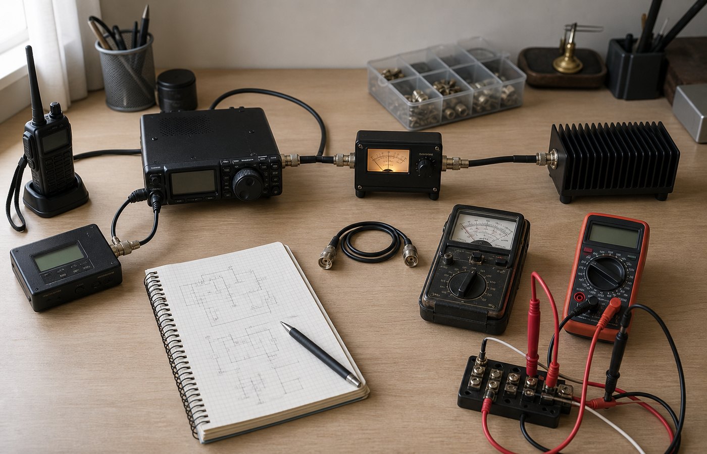
The measuring chain the licence conditions assume: transceiver, through the meter, into a dummy load, with the frequency counter alongside. Everything on this desk can be bought second-hand for less than a new handheld.
The absorption wavemeter
The simplest instrument that measures frequency at all is a tuned circuit with a
detector on it. A coil, a variable capacitor calibrated in frequency, a diode and a
microammeter — nothing else, and no power supply. Hold the coil near the
transmitter's tank or feeder, turn the capacitor, and the meter peaks when the tuned
circuit is resonant at the frequency present. The energy that moves the needle is
absorbed from the transmitter, which is where the name comes from.
An absorption wavemeter. L and the variable capacitor C form the tuned circuit, and the dial on C is calibrated in frequency. The diode rectifies the RF picked up, the small capacitor bypasses what is left of it, and the microammeter reads the resulting DC. Nothing here needs a battery.
Its virtues are that it costs almost nothing, cannot itself radiate, and works on a
dead transmitter's field without any connection. Its vice is accuracy: the tuned circuit
has a modest Q, so the peak is broad and the reading is good to a few per cent at best.
On 7 MHz, three per cent is 210 kHz — hopelessly coarse for checking a band edge, but
perfectly adequate for its real job, which is harmonic hunting. If your
transmitter is on 7 MHz and the wavemeter also peaks strongly at 14 and 21 MHz when held
near the feeder, you have a harmonic problem and the low-pass filter needs
attention.
The heterodyne frequency meter
Far better accuracy comes from comparing the unknown against a known. A heterodyne
frequency meter contains a calibrated variable oscillator. Its output is
mixed with the signal being measured and the difference is fed to headphones. Tune the
internal oscillator towards the unknown frequency and you hear a beat note falling in
pitch; when the two frequencies coincide the note falls to nothing. That is
zero beat, and the frequency is then read off the calibrated dial.
The ear is a remarkably good null detector — a trained operator can judge zero beat to
within a few tens of hertz — so the method is orders of magnitude better than an
absorption wavemeter. Its accuracy is limited entirely by how good the internal
oscillator's calibration is, which is why such a meter carries a built-in crystal
reference for checking itself. Modern equivalents use the receiver you already own: tune
your rig to the transmitted signal, and its calibrated dial does the same job.
The grid-dip meter
A dip meter is the opposite arrangement: a small variable-frequency oscillator with its
coil exposed, and a meter reading the oscillator's own current. Hold the coil close to a
tuned circuit and sweep. When the oscillator reaches the resonant frequency of the circuit
under test, that circuit absorbs energy from it, the oscillator's current falls, and the
meter dips. The name comes from valve days, when the meter read grid
current; the modern transistor version is a gate-dip meter, and the technique is
identical.
Its value is that the circuit under test is not powered. That makes it
the instrument of choice for:
finding the resonant frequency of a tank circuit or an IF transformer on the bench;
checking where an antenna or a trap actually resonates before any RF is applied;
measuring an unknown coil or capacitor, by resonating it against a known one;
finding the frequency of a dead oscillator, which is how you diagnose one that will
not start.
Switched to passive mode, with its own oscillator off, a dip meter also works as an
absorption wavemeter.
The digital frequency counter
A counter does exactly what the name says: it opens a gate for a precisely known
interval, counts the input cycles that arrive during it, and divides. Open the gate for
one second and the count is the frequency in hertz.
frequency = number of cycles counted ÷ gate time
hertz = cycles ÷ seconds
Frequency is the cycle count divided by the length of the gate.
Everything therefore depends on the gate being exactly as long as it claims, and the
gate is derived from a crystal oscillator — the timebase.
The accuracy of a counter is set entirely by the accuracy of its timebase,
not by how many digits it displays. An eight-digit counter with a drifting crystal
displays eight digits of nonsense.
Worked example — what the timebase costs you
A counter's timebase is specified as accurate to ±1 part per million. You measure a 2 m
signal at 145.000 MHz. How much might the reading be out?
145 000 000 × 0.000001 = 145 Hz
So the true frequency is somewhere within ±145 Hz of the display, whatever the last
digits say. A cheap counter specified at ±10 ppm would be ±1450 Hz on the same signal —
still far better than any wavemeter, and easily good enough to prove you are inside
144–146 MHz.
The gate-time trade-off
A longer gate counts more cycles and so resolves the frequency more finely, but you
wait longer for each reading. A one-second gate gives 1 Hz resolution and one reading per
second. A 0.1-second gate gives 10 Hz resolution and ten readings per second, which is
what you want when you are turning a trimmer and need to see the effect immediately. There
is also an unavoidable ±1 count uncertainty on the last digit, because
the gate does not open in step with the incoming cycles. Short gate for adjusting, long
gate for the final reading.
The crystal calibrator and marker generator
A crystal calibrator is a crystal oscillator, usually at 100 kHz, deliberately run so
that its output is a distorted waveform rich in harmonics. Those harmonics appear as
markers every 100 kHz all the way up through HF. Tune the receiver until
you hear a marker, and you have a point of known frequency against which to check the
dial. Many units divide down to give 25 kHz or 10 kHz markers as well.
The practical use is the one the licence condition demands: before transmitting near
the edge of a band, find the marker that sits on the band edge and confirm which side of
it you are. On an older analogue transceiver this was the standard pre-transmission
check.
Calibrating against a standard
All of the above are only as good as their own calibration, so at some point every
station needs an external reference. Standard frequency and time signal stations exist for
exactly this purpose. They transmit on 5, 10 and 15 MHz among others, are controlled by
atomic standards, and are the ultimate check available to an amateur: zero-beat your
calibrator against one and its accuracy becomes yours. A broadcast station's carrier is
well controlled but is not published to any guaranteed tolerance, and the mains frequency
wanders by a fraction of a hertz all day, so neither is a substitute. The
time signals lesson covers the stations themselves and
how their time codes are read.
The rest of the bench, briefly
The multimeter
The heart of an analogue multimeter is a moving-coil movement: a coil
suspended in a magnetic field, deflecting against a spring by an amount proportional to
the current through it. It is fundamentally a sensitive current meter, typically
full-scale at 50 µA, and everything else is built around it.
To make
Add
Connect
Ammeter
A low-value shunt resistor in parallel with the movement, so most of the current bypasses it
In series with the circuit
Voltmeter
A high-value multiplier resistor in series with the movement, which drops most of the applied voltage
Across (in parallel with) the circuit
A voltmeter must have a high resistance, because whatever current it
draws is current taken from the circuit being measured. Connect a low-resistance voltmeter
across a high-resistance potential divider and it loads the divider, changes the very
voltage it is there to read, and gives you a confidently wrong answer. The old figure of
merit for this is ohms per volt: 20 000 Ω/V was a good analogue meter; a modern
digital multimeter presents 10 MΩ on every range and the problem largely goes away.
SWR meter, power meter, dummy load and oscilloscope
Instrument
What it measures
Where it goes
SWR meter / reflectometer
Forward and reflected power separately, using a directional coupler; most are calibrated to read SWR directly
In the feedline, between transmitter and antenna
RF power meter
Power actually delivered. The same directional coupler with a calibrated scale
In the feedline, or into a dummy load
Dummy load
Nothing — it is a non-inductive resistor, usually 50 Ω, that absorbs full output and radiates almost none of it
In place of the antenna, for any test over 30 seconds
Oscilloscope
The waveform itself against time — the RF envelope, so flat-topping and overmodulation are visible
Lightly coupled to the output, or across an audio stage
Two points worth carrying away. An SWR meter tells you nothing whatever about
frequency, however prominent it is on the desk — that is a favourite distractor. And the
dummy load is not optional equipment: the licence conditions permit tests of not more than
30 seconds on the air, and require an artificial aerial beyond that. The
bench tools on this site do the arithmetic that goes with these
instruments.
Practice
Check yourself
1 / 10
Loading questions…
Kept in this browser only. Nothing is uploaded, and there is no account to make.
On the plan, not yet built
Should these lessons have video too?
Thirty-six lessons is the better part of eight hours of footage, and it is
only worth recording if people would actually watch it rather than read.
One tap tells me. Nothing else is asked of you.