There is no best aerial, only the best aerial for a band, a space and a purpose. A rotatable Yagi is a magnificent thing on 20 m and an absurdity on a Mumbai balcony; a rubber duck is hopeless from indoors and exactly right clipped to your belt at a rally. This lesson goes through the aerials the syllabus names, and for each one asks the same four questions: what is it, what shape does it radiate, what does it feed at, and what does it buy you. The examiner asks about the Yagi more than all the others put together, so that section is the long one.
Reading a radiation pattern before we start
A radiation pattern is a polar graph of relative field strength against direction: distance from the centre means signal strength that way, not distance in kilometres. Two slices are usually shown — the azimuth plan view looking down, and the elevation slice from the side. Choose an aerial in the gallery below and its pattern is drawn on the same grid every time, with the half-wave dipole left as a faint outline behind it so you can see what has been given up to gain what.
Radiation patterns same grid, six aerials
selected aerial half-wave dipole, for shape comparison
- Typical gain
- —
- Front-to-back
- —
- Polarisation
- —
- Feed impedance
- —
Every outline is plotted from the standard free-space expression for that aerial, as relative field strength on a linear scale. It shows the shape honestly; it is not a measured range plot, and no real aerial escapes the influence of the ground under it.
Keep one principle in mind while you play with it: an aerial makes no power. Every decibel of gain in one direction has been taken away from some other direction. The feed impedances quoted below matter because the feeder has to be matched to them, which is the subject of the next lesson.
The dipole family
Half-wave dipole
The reference against which everything else is measured, and the aerial most Indian
amateurs start with. Two legs of wire totalling 142 ÷ f (MHz) metres, fed at
the centre, about 73 Ω, pattern a figure of eight broadside to
the wire with deep nulls off the ends, gain 0 dBd by definition. Cheap,
predictable, and hard to beat for the money. The
previous lesson covers its cutting and its current
distribution.
Inverted V
The same dipole with its centre insulator hoisted to the top of a single mast and both legs sloping down to low anchor points, typically at an included angle of about 120 degrees. Its decisive advantage is mechanical: it needs only one high support instead of two, which on a small plot or a flat roof is often the difference between having an aerial and not having one. The sloping legs fill in the end nulls, so the pattern becomes more nearly omnidirectional, and they drop the feedpoint impedance conveniently towards 50 Ω.
Folded dipole
A half-wave dipole with a second conductor joined across both ends and spaced a few centimetres away, the feeder connecting to a break in the middle of one side only. The current now divides between two conductors, so for the same radiated power the feedpoint sees half the current at the same voltage — and impedance goes up four times:
4 × 73 Ω ≈ 300 Ω
That is a direct match to 300 Ω twin lead, which is why television aerials use it, but what matters more to an amateur is bandwidth: the fatter effective conductor keeps the SWR usable right across a wide band like 10 m instead of climbing at the edges. It is also a robust, DC-continuous loop, so static cannot build up on it in a dusty pre-monsoon wind. Both are why it is the standard driven element in a good Yagi.
Verticals
Quarter-wave ground plane
A single quarter-wave radiator standing on a ground plane — either real earth with buried radials, or three or four quarter-wave wires at the base of a mast-mounted one. The ground supplies the mirror image of the missing half, so it behaves as half a dipole and feeds at about 36 Ω with horizontal radials, rising towards 50 Ω when they are sloped down. The pattern is a circle in azimuth — omnidirectional, with no nulls to exploit — and low in elevation, which makes a vertical a good DX aerial and a poor one for local work on 40 m. On a vehicle the bodywork is the ground plane, which is why a mag-mount in the middle of the roof beats one on the boot lid. The whole thing lives or dies by its radials: two rusty ones make a heater, a dozen good ones make a DX machine.
The 5/8 wave vertical
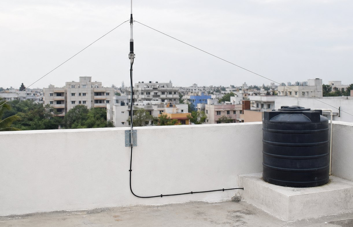
Stretch the radiator to five-eighths of a wavelength and the vertical pattern is squashed further down towards the horizon, giving roughly 3 dB over a quarter-wave. Five-eighths of a wavelength is not a resonant length, so the feedpoint is strongly reactive and a loading coil at the base is needed to cancel that out before the feeder sees anything usable. This is the standard 2 m mobile and base whip in India: a 5/8 on 145 MHz is about 1.3 m of stainless steel, it clears every rooftop water tank in the neighbourhood, and its low angle is exactly what you want for reaching a repeater 40 km away.
The Yagi-Uda array
Invented at Tohoku University by Uda and published in English by Yagi, this is the directional aerial everyone recognises from a rooftop television installation. Only one element is connected to the feeder — the driven element, usually a dipole or folded dipole. The rest are parasitic: they carry current only because the driven element induces it in them, and their length sets the phase of that current.
| Element | Length | Position | Behaves as |
|---|---|---|---|
| Reflector | ≈ 0.55 λ — longer | Behind the driven element | Inductive; it pushes energy forward |
| Driven element | ≈ 0.5 λ | Fed by the transmitter | Resonant |
| Director(s) | ≈ 0.45 λ — shorter | In front | Capacitive; they pull energy along |
Element spacing is usually 0.15 to 0.25 wavelengths, and a Yagi normally has exactly one reflector — a second one adds almost nothing — but as many directors as the boom will hold. Two figures describe how well it works: gain, its advantage over a dipole in the forward direction, and front-to-back ratio, how much weaker it is behind than in front. Both improve as elements are added, but what really buys gain is boom length: cramming more elements onto a short boom gains you very little. As a rough guide, three elements give around 5 dBd and a doubling of boom length is worth roughly another 2.5 dB, with diminishing returns all the way.
Why does it have gain at all? Not because it radiates more power — it cannot. It concentrates the radiated power into one direction. That is the examiner's own phrasing and it is the whole explanation, and it also explains the front-to-back ratio: the energy in the forward lobe is the energy missing from the back.
Cubical quad
A quad element is a full-wavelength loop of wire bent into a square on a fibreglass or bamboo spreader, so each of the four sides is a quarter wavelength. Like a Yagi it uses one driven loop with a parasitic reflector behind it, and directors may be added. It gives gain comparable to a Yagi with one more element, at a lower angle of radiation for the same mast height — the classic reason for choosing a quad on a crowded plot. It is lighter than a Yagi, but presents far more surface to the wind and is fussier to keep in one piece through a monsoon.
Loops
The full-wave loop above is a transmitting aerial. A small receiving loop is a different animal: a few turns of wire much smaller than a wavelength, often tuned with a capacitor. It responds chiefly to the magnetic component of the wave, which makes it far less sensitive to the electrical noise that saturates an Indian urban street — switch-mode chargers, LED drivers, unshielded cables. Its pattern is a figure of eight with very sharp nulls through the plane of the loop, so rotating it can null a single interfering source almost completely. That null, not gain, is the point: it is the classic direction-finding aerial, and with poor gain it stays a receiving aerial rather than a transmitting one.
Long wire and end-fed half wave
A long wire means a wire genuinely long compared with the wavelength — one wavelength or more, not merely a long piece of wire. Fed at one end against an earth or counterpoise through an ATU, it works on many bands at once, which is its whole appeal to someone who cannot put up several dipoles. The price is a pattern that breaks into multiple lobes, sharper and less predictable as the wire lengthens, and an earth that must be good or the losses are severe. Two long wires in a horizontal V, fed at the apex, make a V-antenna, which fires along the bisector and is genuinely directional.
An end-fed half wave is a different idea: exactly half a wavelength of wire, fed at a voltage maximum, so the feedpoint impedance is several thousand ohms instead of 73. A step-down transformer at the feedpoint — a 49:1 is common — brings that down to something coax can carry. It needs no radial field, only a short counterpoise, which is why it has become the favourite portable and balcony aerial.
Parabolic dish
At microwave frequencies a reflector many wavelengths across can be used, and a parabola focuses everything arriving parallel to its axis onto a single feed point. Gain depends on how many wavelengths wide the aperture is:
G ∝ (π D ÷ λ)² — gain rises with the area of the dish and with the square of the frequency
Double the diameter and the gain goes up four times, or 6 dB. Keep the dish and double the frequency and the gain also goes up four times, because the same metal is now twice as many wavelengths across. That relationship is why dishes are practical only at SHF and above: a dish with useful gain on HF would be hundreds of metres across.
Helical
A helix wound on a supporting cylinder in front of a ground-plane reflector, with a circumference of roughly one wavelength, radiates along its axis with circular polarisation — the E field rotates as the wave travels. That makes it indifferent to the orientation of the far-end aerial, exactly what satellite work needs when the spacecraft is tumbling. It is broadband and easy to build, and both ends must use the same hand of rotation: right-hand circular does not talk to left-hand circular.
Whips and the rubber duck
A whip is a vertical rod, usually a quarter wave, used where nothing larger will fit — on a vehicle, or a rooftop with no room for radials. For HF it is almost always shortened and brought back to resonance with a loading coil, and it works, after a fashion.
The rubber duck on your handheld takes that idea to its limit. A quarter wave on 2 m is about 49 cm and nobody will carry that on their belt, so the duck is a heavily shortened, coil-loaded aerial a fraction of the length: low radiation resistance, unchanged loss resistance, and several decibels thrown away against a full-size whip. The loss is not theoretical. Clip a full-length telescopic whip to the same handheld, or run a few metres of coax to a 5/8 on the terrace, and stations that were unreadable become comfortable copy. If you buy one accessory for a new handheld, buy an aerial.
The artificial aerial — the one you must own
A dummy load, which the rules call an artificial aerial, is a non-inductive resistor of 50 Ω in a housing that can get rid of the heat. It presents the transmitter with a perfect match while radiating essentially nothing, so you can tune up, measure power, test a repair or demonstrate a rig without putting a signal on the air. It is the only “aerial” the licence conditions actually oblige you to have.
All of them at a glance
| Aerial | Pattern | Typical gain | Feed Z | Where it earns its place |
|---|---|---|---|---|
| Half-wave dipole | Figure of eight, broadside | 0 dBd | 73 Ω | The first aerial, and the reference for all gain figures |
| Inverted V | Nearly omnidirectional | ≈ 0 dBd | ≈ 50 Ω | Only one high support needed — the small-plot dipole |
| Folded dipole | Same as a dipole | 0 dBd | ≈ 300 Ω | Wide bandwidth; matches 300 Ω ribbon; Yagi driven element |
| Quarter-wave ground plane | Omnidirectional, low angle | ≈ −1 dBd | 36 Ω, or 50 Ω with sloping radials | DX and all-round coverage with no rotator |
| 5/8 wave vertical | Omnidirectional, lower angle still | ≈ 3 dB over a quarter-wave | Needs a base loading coil | The standard 2 m mobile and base whip |
| Yagi-Uda | One forward lobe, small back lobe | 5 dBd upwards with element count | Matched to 50 Ω at the driven element | Gain and front-to-back where you can rotate it |
| Cubical quad | Like a Yagi | Similar to a Yagi with one more element | ≈ 50–100 Ω | Low angle from a low mast |
| Small receiving loop | Figure of eight with very sharp nulls | Negative | Tuned, matched locally | Low-noise receiving and direction finding |
| Long wire | Multiple lobes | Modest, unpredictable | High; needs an ATU | Many bands from one wire and one earth |
| End-fed half wave | Like a dipole | ≈ 0 dBd | Several kΩ, via a 49:1 transformer | Portable and balcony work; no radial field |
| Parabolic dish | Very narrow pencil beam | Tens of dB | Set by the feed | Microwave only — SHF and above |
| Helical | Axial beam, circular polarisation | 10–15 dBi typical | Broadband, near 140 Ω | Satellites and any tumbling far end |
| Rubber duck | Roughly omnidirectional, poor | Several dB below a quarter-wave whip | Matched by its loading coil | Portability, and nothing else |
| Dummy load | None — it must not radiate | — | 50 Ω resistive | Testing, tuning, and the licence conditions |
Practice
Check yourself
1 / 12
Loading questions…
Kept in this browser only. Nothing is uploaded, and there is no account to make.
On the plan, not yet built
Should these lessons have video too?
Thirty-six lessons is the better part of eight hours of footage, and it is only worth recording if people would actually watch it rather than read. One tap tells me. Nothing else is asked of you.